Based on the versions described in the Vacuum Cleaner Application page, the agent requires multiple inputs and outputs:
- Inputs:
dirty,button_start, andfull_deposit. - Outputs:
pos_1,pos_2,pos_3,pos_3,suck, andempty(empty dust deposit).
Although the NodeMCUv3 board has 16 GPIOs pins available, only a small portion of these can be used for standard digital input/output. Many GPIO pins are used for dedicated functions/signals, such as RX, TX, SPI_CLK, and others. For this reason, 5 pins are used for digital output of the pos_1, pos_2, pos_3, pos_4, and suck & empty beliefs and the analog input is used for the dirty, button_start, and full_deposit inputs.
The diagram below shows the circuit connected to the NodeMCUv3:
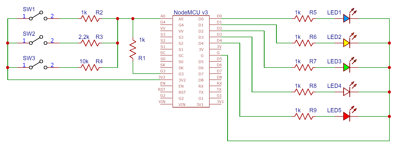
Where:
- SW1:
button_start - SW2:
dirty - SW3:
full_deposit - LED1:
pos_1 - LED2:
pos_2 - LED3:
pos_3 - LED4:
pos_4 - LED5:
suck&empty
The LEDs 1~4 will emit light according to the location of the vacuum cleaner, while LED5 will blink when the vacuum is sucking or emptying the dust deposit.
When closed, the switches set the value of the corresponding belief to true. Similarly, the value is set to false if the switch is open. The following table displays the values read by the analog input for different combinations of switch states:
SW1 (button_start) |
SW2 (dirty) |
SW3 (full_deposit) |
Value |
| 0 | 0 | 0 | 10 |
| 0 | 0 | 1 | 116 |
| 0 | 1 | 0 | 368 |
| 0 | 1 | 1 | 423 |
| 1 | 0 | 0 | 589 |
| 1 | 0 | 1 | 615 |
| 1 | 1 | 0 | 693 |
| 1 | 1 | 1 | 715 |